 |
RAMSES Documentation
27.0.130
Information for RAMSES users and developers
|
|
RAMSES Documentation
27.0.130
Information for RAMSES users and developers
|
RAMSES SDK provides a text creation layer on top of RAMSES that allows user to create meshes representing text glyphs that can be used as part of a RAMSES scene. Freetype2 fonts are supported with optional Harfbuzz reshaping.
Text meshes are 3D meshes like any other RAMSES meshes. By using orthographic projection and a suitable transformation matrix text can also be renderered as an overlay on top of the screen. To achieve this, the transformation matrix must use the screen surface's width and height in pixels.
Font provides a glyph bitmap for a glyph code for each character. RAMSES text layer API uses Unicode (UTF32). Upon creation, characters are cached to save the performance of creating the same character mutliple times. RAMSES stores glyph bitmaps in a special format that only uses 8 bits in the red channel. The values in the red channel are intepreted as alpha channel in the shader.
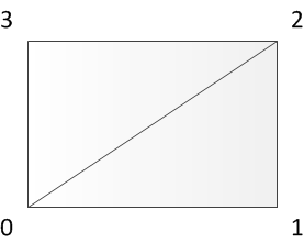
Text objects are made up of lines consisting of one or multiple glyphs. Each glyph is built upon two triangles in the size of the glyphs bounding box. The winding of the vertices is counter-clockwise. ( 0-1-2 for the first triangle and 0-2-3 for the second triangle )
All the glyphs requested at runtime are stored in a glyph map. The glyph map is implemented as a texture atlas. Each vertex of the text geometry provides texture coordinates that will project the glyph bitmap onto the geometry. For each rasterized pixel there is a lookup in the glyph texture. The color provided using the input object will be used for the red, green and blue channels. The content of the glyph map is used for the alpha channel. This way glyphs can be rasterized using the color depth of the glyph map using a color provided by the user.
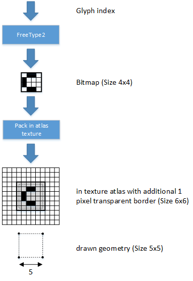
The following diagram depicts the storage of the bitmap data in a texture atlas with the according geometry, drawn for the glyph. The font engine delivers a monochrome bitmap of the requested glyph. This data is packed into a texture atlas with an additional transparent border of one pixel on each side. Thus, a glyph of size 4x4 takes 6x6 texel place in the texture atlas. The vertices of the drawn geometry are centered into this transparent border texels, so the size of the drawn quad is 5x5 for the given example. The vertex positions are also centered to the midpoint of screen pixels, unless there is no additional transformation, and an orthographic projection is used. That way, each pixel will result in exactly the original transparency value, computed by the font engine. This is also true, when bilinear filtering is active. Bilinear filtering should be activated for rotated or scaled text, to achieve good rendering quality. The one pixel border is needed for the case, when the glyph bitmap is filtered.
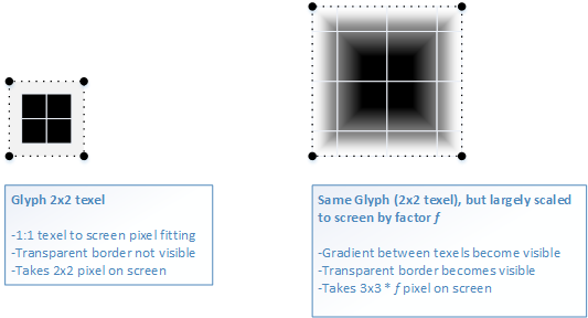
The picture below depicts the difference of an unscaled glyph versus the same glyph beeing scaled largely by a scale factor. The example glyph consists of 2x2 black texels. When it is rendered unscaled to the screen - shown on left side - it will exactly take 2x2 pixels space. The half pixel transparent border has no influence here. In contrast on right side, when a scale factor f is applied to blow up the glyph's geometry, the linear gradient between texels become visible in rendering, and now the half texel transparent border will also become visible. The rendering of the glyph takes 3x3 multiplied by the scale factor f pixels on screen.
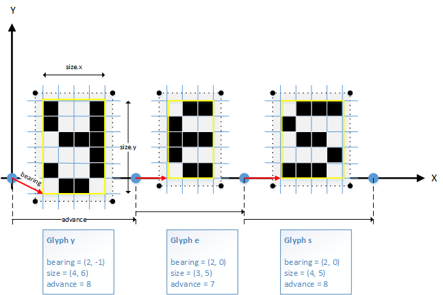
Beside the bitmap data, each glyph has additional metric information (bearing, size and advance), that is needed to place the glyph at the right position. The following picture shows the three glyphs for the string "yes". The geometry generation starts for the first glyph, with the so called current pen position in the origin (0,0). The bearing vector of the glyph is added to the current pen position, as shown by the red arrows. This gives the lower left corner of the positioned glyph. The size of the glyph is the horizontal and vertical number of pixels, which are stored for that glyph in the texture atlas. As described above, the final geometry is offseted by 0.5 pixel in x and y direction, because of the additional 1 pixel transparent border around the glyph. After positioning one glyph, it's advance value is added to the current pen position for placing the next glyph.
In order to create a renderable mesh representing text, the mesh has to have a valid shader. User needs to provide a RAMSES effect that will be assigned to both GeometryBinding and Appearance created by the text logic. The effect has to have semantics assigned to various uniform and attribute inputs so that the text logic knows where to bind necessary inputs like vertices, texture coordinates and sampler with glyph texture. These are the semantics required for text:
Check the text example to see typical text shader usage, generally shader can have any logic and can be customized to fit user's needs. Similarily Appearance's properties can be arbitrary but typically use alpha blending and no depth test if used as 2D overlay.